Introduction
Sheet metal under 3mm thickness demands exceptional welding precision—one wrong parameter and you're facing burn-through, warping, or scrap material. According to industry research, inadequate welding techniques directly correlate with increased defect rates in thin materials, particularly in automotive, aerospace, and tool and die sectors where quality standards leave no margin for error.
These challenges intensify with TIG welding, where thin gauges demand precise heat control. The primary risks include burn-through (complete melting through the base material), warping from excessive heat input, and difficulty maintaining stable arc control.
Materials under 3mm thickness heat up rapidly, increasing distortion and requiring the precision techniques that professional micro-welding services use to maintain defect rates below 1%.
This guide provides expert techniques to overcome these challenges, covering everything from equipment setup to advanced heat control methods that professional welders use for zero-defect results.
Key Takeaways
- Control amperage precisely (30-70 amps for materials under 1/8") and manage heat strategically to prevent warping
- Clean surfaces thoroughly, maintain tight fit-ups, and use backing materials to avoid burn-through
- Use pulsed TIG and foot pedal control to reduce heat input and improve weld quality
- Apply skip welding patterns and downhill techniques to minimize heat buildup
- For critical mould and die repairs, certified welding ensures structural integrity and production uptime
Understanding TIG Welding for Sheet Metal
Why TIG is Preferred for Thin Materials
Gas Tungsten Arc Welding (GTAW), commonly known as TIG, is the gold standard for joining precision components in industries where appearance and metal quality are critical.
TIG separates the heat source from filler metal addition, providing exceptional control over the weld puddle.
Key advantages for sheet metal:
- Precise arc control at low amperage settings (as low as 15 amps)
- Clean welds with no slag, spatter, or post-weld cleanup
- Narrow heat-affected zone (HAZ) reduces distortion risk
- Independent control of heat input and deposition rate
- Superior weld appearance for visible applications
Defining Sheet Metal Thickness
In welding terminology, "sheet metal" typically refers to materials under 3mm (approximately 1/8") thick. This threshold matters because thinner materials require fundamentally different techniques than structural welding.
The rapid heat absorption in thin gauges creates a narrow window between insufficient fusion and complete burn-through.
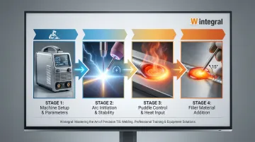
The TIG Process for Thin Materials
The TIG process uses a non-consumable tungsten electrode to create an electric arc between the electrode and workpiece. An inert shielding gas (typically argon) protects the molten weld pool from atmospheric contamination.
The welder controls the torch with one hand and feeds filler rod with the other, allowing precise control over both heat input and metal deposition—critical factors when working with materials that can burn through in milliseconds.
Essential Preparation Before Welding
Surface Preparation and Cleaning
Surface cleanliness is non-negotiable for quality TIG welds on thin materials. Research shows that even 1% air entrainment in shielding gas can cause distributed porosity, and surface contaminants dramatically increase this risk.
Proper cleaning procedures:
- Steel and stainless steel: Remove mill scale, oils, and rust using dedicated stainless steel wire brushes (never use brushes contaminated with other metals)
- Aluminum: Mechanically remove oxide layer immediately before welding; use solvents like acetone or denatured alcohol to eliminate oils
- All materials: Clean 1-2 inches on both sides of the joint; wipe with lint-free cloth after mechanical cleaning
Contaminants cause porosity, weak welds, arc instability, and tungsten contamination—all of which compromise structural integrity in thin materials where there's minimal margin for defects.
Material Fit-Up and Joint Design
Once surfaces are clean, focus on fit-up—critical for thin sheet metal success. Gaps should not exceed the material thickness, and ideally should be minimal.
Poor fit-up forces you to add excessive filler metal, which increases heat input and burn-through risk.
Optimal joint designs:
- Butt joints: Most common for thin materials; requires precise edge preparation and alignment
- Lap joints: Provides more material thickness at the joint; easier to control burn-through
- Edge joints: Used for very thin materials; often welded without filler metal
Use clamps or fixtures to maintain alignment throughout the welding process. Even slight movement during welding can create gaps that lead to defects.
Equipment Setup and Settings
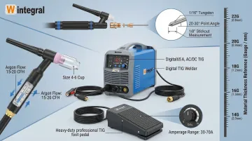
Essential equipment checklist:
- TIG welder with adjustable amperage and foot pedal or fingertip control
- Tungsten electrode: 1/16" (1.6mm) or 0.040" (1.0mm) diameter for most sheet metal
- Filler rod: 1/16" diameter or smaller, matched to base metal composition
- Gas cup: Size 4, 5, or 6 for adequate shielding coverage
- Shielding gas: Pure argon for steel/stainless; pure argon for aluminum with AC
Initial amperage settings:
Follow the general rule of 1 amp per 0.001" of material thickness. For example, 0.050" material starts at about 50 amps. Begin 10-20% lower than calculated to prevent burn-through, then adjust upward based on puddle formation.
Tungsten electrode preparation:
Use 2% ceriated or lanthanated tungsten for DC applications (steel/stainless). Grind the electrode to a sharp point with a 20-30 degree included angle for thin materials—this concentrates the arc for precise control.
Maintain 1/8" or less electrode stickout beyond the gas cup.
10 Expert Tips for TIG Welding Sheet Metal
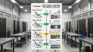
Tip 1: Master Heat Control with a Foot Pedal
Foot pedal control gives you real-time amperage adjustment without removing your hands from the torch or filler rod. When welding sheet metal, heat buildup happens in seconds—making this control essential.
Proper foot pedal technique:
- Start low: Begin with 20-30% pedal depression to establish the arc without immediately burning through
- Ramp up gradually: Increase amperage until a puddle forms, typically reaching 60-80% of maximum setting
- Modulate constantly: Reduce amperage when heat builds up; increase when the puddle cools or you're welding over tack welds
- Finish clean: Decrease amperage gradually at the end of the weld while adding filler to prevent crater cracks
This dynamic control prevents the cumulative heat buildup that causes warping and burn-through in continuous welds.
Tip 2: Use Pulsing to Minimize Heat Input
Pulsed TIG welding alternates between high peak current (which melts the metal) and low background current (which allows cooling). This technique reduces overall heat input, minimizes distortion, and creates a narrower heat-affected zone compared to constant current welding.
Recommended pulse settings for sheet metal:
- Pulse frequency: 50-150 pulses per minute (start at 1-2 Hz and adjust)
- Peak current: 20-40% higher than the background current
- Background current: Set to maintain the arc without adding significant heat (typically 40-60% of peak)
Adjust based on material response—you should see distinct ripples in the bead corresponding to each pulse cycle. Pulsing is particularly effective for stainless steel and aluminum sheet metal where distortion control is critical.
Tip 3: Choose the Right Tungsten Electrode
Your tungsten electrode choice directly impacts arc stability and heat concentration.
Electrode sizing rule: Never use tungsten larger than your material thickness. For most sheet metal work under 1/8":
- 0.040" (1.0mm): Very thin materials (under 0.040" thick), amperage range 15-80A
- 1/16" (1.6mm): Standard for materials 0.040"-0.125" thick, amperage range 70-150A
Electrode type selection:
- 2% ceriated or lanthanated: Best for DC applications (steel, stainless steel); provides excellent arc starting and stability at low amperage
- Pure or zirconiated: Required for AC aluminum welding; maintains a rounded tip during AC operation
Grind the electrode to a sharp point (20-30 degree included angle) for thin materials. A sharp point concentrates the arc into a smaller area, providing the precise heat control necessary for sheet metal.
Tip 4: Perfect Your Torch Angle and Position
Torch positioning dramatically affects heat input and weld pool control.
Optimal torch angle:
- Work angle: 70-80 degrees to the work surface for butt welds
- Travel angle: Slight drag angle of 10-15 degrees in the direction of travel (for downhill welding on thin materials)
Arc length discipline:
Maintain 1/8" or less arc length—approximately the diameter of your tungsten electrode.
Shorter arc length provides more focused heat, better penetration control, and reduced contamination risk. Extending the arc increases voltage and overall heat input, widening the bead and reducing your control—exactly what you want to avoid on thin materials.
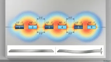
Tip 5: Employ Skip Welding or Tack Welding Patterns
Continuous welding creates cumulative heat buildup that causes warping in thin materials. Skip welding distributes heat across the joint, allowing sections to cool before adjacent areas are welded.
Skip welding technique:
- Weld short segments of 1/2" to 1" length
- Skip ahead 2-3 inches and weld another segment
- Continue this pattern along the entire joint
- Return to fill the gaps between initial segments after they've cooled
Tack welding approach for very thin materials (under 0.050"):
- Place small tack welds every 1/2" to 1" along the joint
- Allow tacks to cool completely
- Return to connect the tacks with minimal filler addition
- The tacks act as heat sinks and maintain alignment
These patterns prevent the progressive heat buildup that causes the "potato chip" warping common in continuous sheet metal welds.
Tip 6: Weld Downhill on Thin Materials
Why fight gravity? Downhill (forehand) welding allows faster travel speeds with less heat input. The technique significantly reduces burn-through risk compared to uphill welding.
Downhill technique:
- Position the joint so you're welding from top to bottom or in a slightly downward direction
- Use a 10-15 degree drag angle (torch pointing in direction of travel)
- Travel faster than you would for thicker materials—the puddle should flow smoothly without excessive spreading
- Add filler rod to the leading edge of the puddle in a consistent dabbing motion
This technique is most effective for materials under 1/8" thick. For thicker materials, uphill welding provides better penetration, but on sheet metal, the reduced heat input of downhill welding is more important.
Tip 7: Select Proper Shielding Gas
Shielding gas selection affects arc characteristics, penetration, and weld quality.
Gas options for sheet metal:
- Pure argon (most common): Provides stable arc, smooth puddle control, and adequate shielding for steel and stainless steel
- Argon/helium mix (75% Ar / 25% He): Increases heat input for faster travel speeds; typically unnecessary for thin materials where heat control is the priority
- Argon/hydrogen (98% Ar / 2% H₂): Used for stainless steel; improves penetration and bead appearance but requires careful control
Gas flow rate: Set to 15-20 CFH (Cubic Feet per Hour) for most sheet metal work. Too low causes oxidation and porosity; too high creates turbulence that draws atmospheric air into the shielding zone. Use a gas lens for improved coverage and flow stability, especially for materials sensitive to oxidation.
Tip 8: Use a Backing Bar or Heat Sink
Backing bars serve two critical functions for thin sheet metal: they absorb excess heat to prevent burn-through, and they provide mechanical support to maintain alignment.
Backing bar materials:
- Copper: Highest thermal conductivity; excellent heat sink for very thin materials
- Aluminum: Good thermal conductivity; lighter and more available than copper
- Stainless steel: Lower conductivity but provides support without excessive heat extraction
When to use backing:
- Critical for materials under 0.050" thickness
- Materials prone to warping (large, thin panels)
- When full penetration must be precisely controlled
- Butt joints where backside support prevents sagging
Position the backing bar tightly against the backside of the joint. For materials requiring backside shielding (like titanium), use a purge setup with argon or helium to prevent oxidation on the root side.
Tip 9: Control Filler Rod Addition
Excess filler increases heat input and burn-through risk on thin materials. Your rod technique matters.
Filler rod technique:
- Dab into the leading edge of the puddle, not the center—this allows the arc to melt the filler before it contacts the base metal
- Maintain consistent rhythm: Develop a steady dab-pause-dab pattern synchronized with your travel speed
- Use smaller diameter rod: 1/16" or smaller for most sheet metal; smaller rod melts faster with less heat input
- Match filler composition: Use filler alloy matched to or slightly higher strength than the base metal
Autogenous welding (without filler):
For edge joints or very thin materials (under 0.030"), consider welding without filler metal. The arc melts the base metal edges together, minimizing heat input and eliminating the burn-through risk from filler addition.
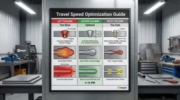
Tip 10: Master Travel Speed
Travel speed directly affects heat input per unit length of weld. Finding the optimal speed is critical for thin materials.
Travel speed indicators:
- Too slow: Excessive heat buildup, widening puddle, burn-through, heavy discoloration on backside
- Too fast: Narrow bead, inadequate fusion, undercut along bead edges, rough appearance
- Optimal: Consistent puddle size (2-3 times material thickness), smooth bead with slight ripples, minimal backside discoloration
Developing proper speed:
Practice on scrap material of the same thickness and composition. Watch the puddle—it should flow smoothly behind the arc without excessive spreading. The leading edge should show a distinct "keyhole" or bright molten area that indicates proper fusion.
For most sheet metal, travel speeds of 6-10 inches per minute are typical, but this varies based on material thickness, amperage, and joint design. Muscle memory comes with practice—focus on puddle appearance rather than counting seconds.
For precision welding applications requiring exceptional control—particularly in tool, die, and mould repair work—these fundamentals become even more critical. At Wintegral Engineering, we apply TIG welding alongside laser and micro-plasma processes for industrial tool repair across India, where sheet metal precision directly impacts production quality.
Common Mistakes and How to Avoid Them
Using too much amperage:
Leads to immediate burn-through on thin materials. Start 10-20% below calculated amperage and increase gradually.
If you burn through, reduce amperage by 5-10 amps and try again.
Inadequate surface preparation:
Contaminants cause porosity, weak welds, and arc instability. Always clean thoroughly with appropriate methods for your base metal.
The few extra minutes spent on preparation prevent hours of rework.
Incorrect tungsten-to-work distance:
Extending the arc creates instability and excessive heat spread. Maintain 3mm (1/8") arc length consistently—approximately the diameter of a 1.5mm (1/16") tungsten electrode.
Continuous welding without cooling time:
Creates cumulative heat buildup causing warping and distortion. Solution: Use skip welding patterns or allow 10-15 second cooling periods between short weld segments.
Oversized filler rod or tungsten electrode:
Creates excessive heat input and poor puddle control. Match electrode and filler size to material thickness—never exceed the base metal thickness with your tungsten diameter.
Welding too slowly:
Surprisingly, welding too slowly increases distortion by putting more heat into the material. Find the optimal travel speed where the puddle flows smoothly without excessive spreading.
When precision matters most:
For critical applications like tool and die repair where tolerances are measured in microns, these common mistakes become even more costly. Companies like Wintegral Engineering combine TIG welding with micro-welding processes to achieve defect rates below 1% on precision repair work. Finding the right balance of amperage, travel speed, and cooling time separates amateur welds from professional results.
When to Use Professional TIG Welding Services
These DIY techniques work well for many sheet metal projects, but certain applications require professional expertise and specialized equipment.
Consider professional services when projects involve:
- Precision mould and die repairs where tolerances reach micron-level accuracy and distortion destroys the tool
- Critical aerospace or medical components requiring certified welders and zero-defect standards
- Complex geometries needing specialized fixturing for distortion control
- Applications where customer specs or regulatory standards require qualified personnel
Wintegral Engineering's Specialized Capabilities
Wintegral Engineering runs a specialized micro-welding facility for mould and die repair, with locations in Bengaluru and Pune.
The team handles multiple welding processes including TIG for thin materials, laser welding, micro-plasma welding, and hybrid techniques developed for precision tool repair.
Professional service advantages include:
- Pulsed TIG systems with precise heat control, specialized fixturing, and backing systems for distortion-free welding
- Decades of combined experience welding precision components from 50 grams to 20 tonnes
- Average welding defect rate below 1%, backed by rigorous inspection protocols
- Quick turnaround times that keep production schedules on track
Major manufacturers including Ashok Leyland, Brakes India, and Wipro use Wintegral's services for critical tool and die repairs where conventional welding would damage expensive precision components.
When failure costs exceed professional service investment, partnering with specialists protects your production quality and reliability.
Frequently Asked Questions
Is TIG or MIG better for sheet metal?
TIG offers superior control and precision for thin materials under 1/8" (3mm), producing cleaner welds with minimal spatter. MIG is faster for thicker sheet metal but requires more skill to avoid burn-through on gauges below 1/16" (1.6mm).
What gas for TIG welding sheet metal?
Pure argon is standard for steel and stainless steel sheet metal. Argon/helium mixes can increase welding speeds but are rarely necessary for thin materials. Aluminum requires pure argon with AC current.
What amperage should I use for TIG welding thin sheet metal?
Use approximately 1 amp per 0.001" (0.025mm) of thickness as a starting point. For example, 0.050" (1.27mm) material starts at 50 amps. Begin 10-20% lower to prevent burn-through, then adjust upward based on puddle formation and penetration. Foot pedal control allows real-time adjustment during welding.
How do I prevent warping when TIG welding sheet metal?
Key techniques include skip welding patterns to distribute heat, tack welds to maintain alignment, and backing bars or heat sinks to absorb excess heat. Pulsed TIG welding significantly reduces distortion compared to constant current. For precision mould and die repair requiring minimal distortion, specialized micro-welding services offer advanced heat control.
What size tungsten electrode should I use for sheet metal?
Never exceed material thickness with your tungsten diameter. Use 1/16" (1.6mm) for materials 0.040"-0.125" (1-3mm) thick, and 0.040" (1.0mm) for very thin materials under 0.040" (1mm). Sharpen to a fine point (20-30 degree included angle) for precise arc control.
Can I TIG weld aluminum sheet metal with the same technique as steel?
No—aluminum requires AC current (not DC), pure or zirconiated tungsten electrode, higher amperage due to thermal conductivity, and aggressive cleaning to remove the oxide layer. Equipment settings and preparation differ significantly from steel.