TIG (GTAW) welding demands meticulous attention to equipment setup, material preparation, and technique refinement. Small adjustments in tungsten preparation, gas flow, or filler rod technique can dramatically impact weld quality and productivity. This guide covers actionable tips and proven techniques that fabricators can implement immediately to improve their TIG welding results, reduce defects, and tackle challenging applications with confidence.
TLDR: Quick Reference for TIG Fabrication Success
- Pure argon at 99.997% purity with 7-9 LPM flow rate prevents weld contamination
- Remove all oils, oxides, and contaminants—use dedicated brushes per material
- Lanthanated tungsten (blue/gold) for most work; zirconiated for AC aluminium
- Arc length matching electrode diameter ensures stable puddle control
- Master the "dab" technique for precise filler addition and superior bead appearance
Understanding TIG Welding Basics for Fabrication
TIG (Gas Tungsten Arc Welding) creates welds using a non-consumable tungsten electrode that generates an electric arc to heat the base metal. An inert shielding gas, typically argon, protects the electrode and molten weld pool from atmospheric contamination. Unlike MIG or stick welding, the welder adds filler metal separately and independently from the arc current, giving precise control over heat input and material deposition.
This precise control makes TIG the preferred choice for fabricators working on precision components. The process produces clean, high-quality welds with no slag, spatter, or smoke.
The concentrated arc creates a narrow heat-affected zone (HAZ), minimizing distortion—critical when working with thin materials or heat-sensitive alloys. TIG welding is extensively used in tool and die repair, mould fabrication, and precision component manufacturing where weld integrity and surface finish are essential.
Key TIG Welding Components
Key TIG welding components include:
- Power source providing DC or AC current depending on material
- TIG torch that holds the tungsten electrode and delivers shielding gas
- Non-consumable tungsten electrode creating the arc
- Filler rod manually fed into the weld pool
- Shielding gas (argon or argon mixtures) protecting the weld
- Foot pedal or amperage control for real-time heat adjustment
Current selection matters:
- DCEN (Direct Current Electrode Negative): Concentrates approximately 70% of heat on the workpiece, ideal for steel, stainless steel, titanium, and copper alloys requiring deep penetration
- AC (Alternating Current): Essential for aluminium and magnesium; the positive half-cycle breaks up surface oxides while the negative half-cycle provides penetration
Essential Equipment Setup Tips
Tungsten Electrode Selection and Preparation
Modern lanthanated tungsten electrodes (blue or gold colour codes) have replaced thoriated types for most applications. They provide superior arc starting, stability, and longevity across both AC and DC welding.
These electrodes eliminate radioactive hazards while maintaining excellent performance.
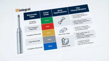
Tungsten Types and Applications:
| Electrode Type | Colour Code | Best For | Key Characteristics |
|---|---|---|---|
| 2% Lanthanated | Blue | AC & DC (all-purpose) | Excellent arc starting, long life, replaces thoriated |
| 1.5% Lanthanated | Gold | AC & DC (general use) | Stable arc, low burn-off rate |
| Zirconiated | White/Brown | AC aluminium | Retains balled tip, resists contamination |
| 2% Ceriated | Grey | Low-amp DC, thin sheet | Good for delicate work under 150 amps |
| 2% Thoriated | Red | DC steel (legacy) | High current capacity but radioactive |
Tungsten preparation technique:
- DC steel/stainless welding: Grind tungsten lengthwise to a sharp 20-30° point to focus the arc and improve penetration. Maintain grinding marks parallel to the electrode length to stabilise the arc
- AC aluminium welding: Use a blunted or flat-tipped point rather than the traditional balled end when using modern inverters with lanthanated tungsten
- Tip: Leave a small flat (land) at the very tip when grinding for high-amperage applications to prevent rapid erosion
Once your tungsten is prepared, proper gas delivery ensures clean, defect-free welds.
Gas Cup and Gas Lens Selection
Manufacturers size gas cups in 1.6mm (1/16-inch) increments—a #5 cup has an 8mm (5/16") internal diameter, whilst a #8 cup measures 12.7mm (1/2").
Select a cup at least three times the tungsten diameter to ensure adequate shielding coverage.
Gas lens advantages:
- Replaces standard collet body with fine mesh screen
- Creates laminar (smooth, non-turbulent) gas flow instead of turbulent flow
- Allows longer tungsten stick-out (up to 25mm) without losing shielding
- Enables lower flow rates whilst maintaining coverage
- Reduces gas consumption and turbulence-related defects
Most fabrication work uses #5-#8 cups. Tighter joints or restricted access may require smaller cups, whilst open joints benefit from larger cups with gas lenses.
Amperage Settings as Starting Points
Use the 1 amp per 0.025mm (0.001 inch) of material thickness rule as your baseline:
- Carbon steel: 1 amp per 0.025mm (e.g., 125 amps for 3mm material)
- Stainless steel: 0.8 amps per 0.025mm (slightly less due to lower thermal conductivity)
- Aluminium: 1.2 amps per 0.025mm (higher due to excellent thermal conductivity)
Adjust based on joint setup, travel speed, and whether you're welding in position. Butt joints typically require more heat than fillet welds, and vertical/overhead positions need 10-15% less amperage than flat welding.
Filler Rod Diameter Selection
Match filler rod diameter to base material thickness for sheet metal applications. The filler rod should almost never exceed the tungsten electrode diameter.
Common filler rod sizes:
- 0.8mm-1.2mm (0.030"-0.045"): Thin materials under 1.6mm, delicate work
- 1.6mm (1/16"): General fabrication standard for materials up to 3mm
- 2.4mm (3/32"): Thicker sections 3mm and above
- 3.2mm (1/8"): Heavy structural work over 6mm
Using slightly smaller filler rod than base material thickness gives better puddle control and allows for more precise heat management.
Material Preparation Techniques for Quality Welds
Surface preparation is the single most effective defect prevention strategy in TIG welding. Contaminants cause porosity, cracking, and weak fusion—problems that no amount of welding skill can overcome.
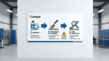
Three-Step Cleaning Process
Step 1: Degrease
- Use acetone or non-chlorinated solvents to remove oils, grease, and cutting fluids
- Apply with clean, lint-free cloths
- Allow to fully evaporate before proceeding
Step 2: Mechanical Cleaning
- Remove oxides, mill scale, and rust with dedicated brushes or abrasives
- Critical rule: Use separate brushes for each material type to prevent cross-contamination
- For stainless steel, use only stainless steel brushes that have never touched carbon steel to prevent iron contamination and rust staining
Step 3: Final Inspection
- Check joint fit-up (gaps should not exceed 1.5mm for most applications)
- Verify all surfaces within 25-50mm of the joint are clean
- Weld immediately after cleaning, especially on aluminum
Material-Specific Preparation
Stainless Steel (304/316):
- Degrease with acetone first
- Use dedicated stainless steel wire brush
- Remove heat tint from previous welds with abrasives or pickling paste
- Back-purge critical joints to prevent sugaring (oxidation on root side)
Aluminum (6061):
Oxide removal is critical—aluminum oxide melts at 3,700°F while base metal melts at 1,200°F. This temperature difference makes proper preparation essential.
Clean with solvent first, then use a dedicated stainless brush. Weld within 30 minutes to prevent oxide re-forming. For heavily oxidized material, chemical cleaning with mild alkaline solutions works well.
4130 Chrome-Moly Steel:
- Remove all mill scale, rust, and paint completely
- Degrease thoroughly—hydrocarbons cause porosity in chrome-moly
- Preheat to 95-205°C for sections over 3mm thick
- Avoid rapid cooling after welding to prevent brittleness
Joint Fit-up Requirements
Tight fit-up is essential for TIG welding quality. Poor gaps lead to:
- Excessive filler metal consumption
- Inconsistent penetration
- Difficulty controlling the weld pool
- Increased distortion
Fit-up tolerances:
- Precision applications (aerospace tubing): 0.00-0.25mm gap maximum
- General fabrication: Up to 1.5mm acceptable with proper technique
- Thicker materials (over 3mm): Bevel edges to 60° included angle for full penetration
Advanced TIG Welding Techniques for Fabricators
Walking the Cup Technique
"Walking the cup" involves resting the ceramic gas cup on the workpiece and rocking it side-to-side to move the torch forward. This technique is widely used in pipe welding to create consistent, uniform weave patterns.
Benefits:
- Maintains constant arc length automatically
- Reduces hand fatigue on long welds
- Creates consistent bead width and appearance
- Improves control in difficult positions
Application: Most effective on pipe and tube welding, especially in fixed positions where maintaining steady hand movement is challenging.
While walking the cup addresses consistency challenges, managing heat input is equally critical for quality welds.
Pulsed TIG for Heat Control
Pulsed TIG alternates between high peak amperage and low background amperage, significantly reducing overall heat input while maintaining good fusion.
Advantages:
- Minimises distortion on thin materials
- Reduces heat-affected zone size
- Improves puddle control in out-of-position welding
- Creates aesthetically pleasing ripple pattern
- Ideal for heat-sensitive alloys like stainless steel and titanium
Settings: Start with 50% background current, 50% duty cycle (equal time at peak and background), and adjust pulse frequency between 0.5-5 pulses per second based on material thickness and travel speed.
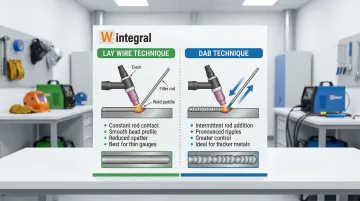
Filler Rod Techniques: Lay Wire vs. Dab
Lay Wire Technique:
- Keep filler rod in constant contact with leading edge of puddle
- Feed continuously as you move forward
- Faster for long, straight welds
- Better for thicker materials requiring high deposition rates
Dab Technique:
- Dip filler rod into puddle, then withdraw
- Add filler in rhythm with your travel
- Superior puddle control and bead appearance
- Essential for thin materials and precision work
- Creates distinct ripple pattern
Most professional fabricators use the dab technique for critical work, switching to lay wire only when speed is prioritised over appearance.
Understanding these filler techniques becomes especially important when working with challenging materials.
Welding Thin Materials (Under 1/16")
Preventing burn-through requires careful heat management:
- Use smaller tungsten (0.040" or 1/16") and finer filler wire (0.030"-0.045")
- Reduce amperage to 30-50 amps depending on material
- Increase travel speed—move quickly once puddle forms
- Consider pulsed TIG to minimise heat input
- Use copper backing bars as heat sinks when possible
Pro tip: Practice on scrap at various amperages to find the minimum heat needed to achieve fusion without melting through.
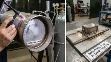
Back-Purging for Critical Applications
Stainless steel and reactive metals oxidise on the backside when exposed to air during welding, creating "sugaring"—a discoloured, weakened root bead. Back-purging with argon replaces oxygen, protecting the root pass:
- Use purge dams, tape, or specialised fixtures to contain purge gas
- For standard applications: reduce oxygen below 1000 ppm (0.1%)
- For pharmaceutical/sanitary applications: achieve 25 ppm or lower
- Allow adequate purge time before striking the arc (typically 2-5 minutes)
- Maintain purge flow until weld cools below 300°F
For precision mould and die repair work requiring contamination-free welds, companies like Wintegral Engineering combine TIG welding with other micro-welding processes to achieve the exact heat control and weld quality needed for critical applications.
Common Mistakes and How to Avoid Them
Contamination Issues
Contamination issues create the most common weld defects for TIG beginners. Understanding these problems helps you avoid costly rework.
Tungsten contamination happens when the electrode touches the molten puddle or filler rod, leaving brittle tungsten inclusions in the weld.
Prevention:
- Maintain proper arc length (about one electrode diameter)
- Keep filler rod angle at 15-20° to the workpiece
- If contamination occurs, stop immediately and regrind the tungsten
Gas shield problems cause porosity and oxidation. Common issues include:
- Flow under 15 CFH causes porosity from atmospheric contamination
- Flow over 25 CFH creates turbulence that pulls air into the shield
- Using argon/CO₂ mixes (MIG gas) instead of pure argon causes porosity and oxidation
- Argon purity below 99.997% leads to weld defects
Heat Control Errors
Heat management separates clean welds from failed joints.
Burn-through happens when excessive amperage or slow travel speed melts through the base metal. Reduce amperage by 10-20% and increase travel speed to fix this.
Cold lap (lack of fusion) occurs when weld metal sits on the surface without fusing to base metal. This comes from insufficient heat, wrong torch angle, or poor fit-up. Increase amperage, adjust torch angle to 70-80° from horizontal, and ensure tight fit-up.
Excessive distortion results from too much total heat input. Use pulsed TIG, skip welding patterns, strategic tack welds, and heat sinks to control warping.
Poor Technique Habits
Incorrect filler rod angle:
- Too steep (over 30°): Difficult to feed smoothly, disrupts gas coverage
- Too shallow (under 10°): Filler doesn't melt properly, creates cold lap
- Best: 15-20° angle pointing toward direction of travel
Inconsistent travel speed:
- Creates uneven bead width and penetration
- Fix: Practice maintaining steady rhythm, use walking the cup technique, or create visual reference points
Improper torch angle:
- Too steep: Reduces gas coverage, causes porosity
- Too shallow: Poor penetration, wide/flat bead
- Best: 70-80° from horizontal (10-20° from vertical)
When to Seek Professional TIG Welding Services
While skilled fabricators can handle most TIG welding tasks, certain scenarios benefit from specialized professional services.
Complex mold repairs requiring precision tolerances under 0.025 mm (25 microns) demand specialized micro-welding equipment and expertise that exceed most shops' budgets to maintain in-house.
Exotic materials like titanium, Inconel, or specialized tool steels often require specific welding procedures, controlled atmospheres, and extensive material knowledge. Specialized providers remove the learning curve and material waste associated with unfamiliar alloys.
Consider professional services when:
- Repair tolerances are tighter than 0.025 mm
- Working with exotic or unfamiliar materials
- Equipment investment exceeds project value
- Time constraints don't allow for technique development
- Critical applications where failure is not an option
For projects meeting these criteria, expert shops provide the necessary capabilities without capital investment.
Wintegral Engineering specializes in precision TIG welding and micro-welding for tool and die repair, serving industries like pressure die casting, plastic injection molding, and metal machining. With facilities in Bengaluru and Pune, they maintain welding defect rates under 1% through quality control processes and multiple welding technologies.
For complex repairs requiring precision beyond standard fabrication capabilities, professional micro-welding services offer cost-effective solutions without specialized equipment investment.
Frequently Asked Questions
What is a TIG fabricator?
A TIG fabricator is a skilled professional who uses TIG (Gas Tungsten Arc Welding) to join metals with precision. They master equipment setup, tungsten preparation, and heat control to produce high-quality welds on stainless steel, aluminum, titanium, and exotic alloys.
What materials can be TIG welded in fabrication?
TIG welding works on nearly all metals including stainless steel (304, 316), carbon steel, aluminum alloys (6061, 5052), titanium, copper, nickel alloys (Inconel), and chrome-moly steel. It excels at dissimilar metal joining and materials requiring clean, precise welds.
What are the most common TIG welding mistakes in fabrication?
The top mistakes include tungsten contamination from touching the puddle, inadequate surface preparation leaving oils or oxides, incorrect gas flow causing porosity, and poor heat control leading to burn-through. Using contaminated brushes between different metals also compromises weld quality.
How do you prepare metal for TIG welding?
Follow a three-step process: First, degrease with acetone or approved solvents to remove oils and cutting fluids. Second, mechanically clean with dedicated brushes or abrasives to remove oxides and mill scale. Third, ensure tight joint fit-up with gaps under 1/16 inch, and weld immediately after cleaning, especially on aluminum.
What tungsten electrode should I use for different metals?
Use 2% lanthanated (blue) or 1.5% lanthanated (gold) tungsten for DC steel and stainless steel welding. For AC aluminum welding, choose pure tungsten or zirconiated (white/brown) electrodes. Match electrode diameter to your amperage requirements.
How do you prevent warping when TIG welding thin materials?
Minimize warping through strategic tack welding in sequence to distribute stress, using copper backing bars as heat sinks, employing skip welding patterns instead of continuous beads, and reducing heat input with lower amperage, pulsed TIG, and faster travel speeds. Clamp or fixture parts firmly to resist distortion forces during cooling.