Introduction
A single incorrect TIG filler rod choice can cost tool and die manufacturers ₹50,000-₹2,00,000 per failed repair in India's precision manufacturing sector. Hot cracking in H13 tool steel repairs, porosity in aluminum injection moulds, or stress fractures in pressure die casting tools trace back to one preventable decision: wrong filler metal selection.
For manufacturers repairing precision dies, moulds, and indexable cutting tools, filler rod selection directly determines weld strength, crack resistance, post-weld machinability, and tool longevity. Incorrect choices lead to costly rework, delayed production schedules, and wasted consumables.
This guide covers essential filler rod selection criteria, material-specific compatibility charts, and sizing strategies to help you achieve defect-free repairs on the first attempt—reducing your average welding defect rate while maintaining the metallurgical integrity your production demands.
Key Takeaways
- Match filler rod composition to base metal chemistry and material thickness
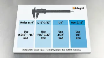
- Rod diameter should equal or be slightly smaller than material thickness
- Common selections: ER70S-6 for carbon steel, ER308L/316L for stainless, ER4043/5356 for aluminum, ER80S-D2 for tool steels
- Correct selection prevents hot cracking, porosity, and brittle welds
What is TIG Filler Rod Selection?
TIG filler rod selection is the process of choosing the appropriate filler metal composition and diameter to match base metal properties, joint requirements, and intended service conditions.
Filler rods are classified by AWS (American Welding Society) designation systems that indicate composition—for example, ER70S-2 for mild steel, ER308L for stainless steel, or ER4043 for aluminum alloys. Getting this selection right prevents weld failures, cracking, and premature corrosion.
Selection involves two primary decisions:
- Filler metal chemistry/alloy type — Ensures metallurgical compatibility with base metal and prevents galvanic corrosion in service
- Rod diameter — Matched to material thickness and joint configuration to maintain proper puddle control and heat input
Incorrect filler rod selection leads to weak joints, post-weld defects, and costly rework in precision applications like mould repair and die restoration.
Key Factors in TIG Filler Rod Selection
Six critical factors determine the optimal filler rod choice, each influencing weld quality, mechanical properties, and long-term performance in precision manufacturing applications.
Base Metal Composition and Compatibility
Filler rod chemistry must be compatible with base metal to prevent galvanic corrosion, achieve proper fusion, and maintain desired mechanical properties. The general rule: match or slightly over-alloy.
When welding dissimilar metals, select a filler rod that bridges the properties of both base materials.
Common pairings:
- 4140 tool steel → ER80S-D2: Provides a good match for strength and balanced ductility, with mandatory preheat (200-300°C) and post-weld heat treatment to prevent martensitic cracking in the heat-affected zone
- 6061 aluminum → ER4043: Preferred for groove welds due to lower crack sensitivity, better fluidity, and a lower melting point compared to ER5356
Material Thickness and Joint Design
Material gauge dictates filler rod diameter. Thinner materials (under 1/8") require smaller diameter rods (1/16"), while thicker sections (1/4"+) use 1/8" to 3/16" rods. Joint type—butt, fillet, or lap—influences rod size selection and deposition rate requirements.
General sizing guidelines:
| Material Thickness | Recommended Rod Diameter | Notes |
|---|---|---|
| < 1/16" (1.6 mm) | 0.045" - 1/16" | Precision control required |
| 1/16" - 3/32" | 1/16" - 3/32" | Match rod to tungsten size |
| 1/8" (3.2 mm) | 3/32" (2.4 mm) | Common for general repair |
| > 3/16" (4.8 mm) | 1/8" (3.2 mm) | Multi-pass welding required |
In precision mold repair applications using micro-TIG, filler wires are available in diameters as small as 0.005 to 0.020 inches for repairing parting lines and delicate details without excessive heat input.
Mechanical Property Requirements
Application stress, impact loads, and service conditions determine whether filler rod should match, undermatch, or overmatch base metal strength. There's a trade-off: higher strength typically means lower ductility.
Tensile strength ranges by classification:
- ER70S series: 480 MPa (70,000 psi) minimum tensile strength
- ER80S series: 550 MPa (80,000 psi) minimum tensile strength
- ER90S series: 620 MPa (90,000 psi) minimum tensile strength
Matching strength is generally desirable for tool repair to ensure uniform thermal and mechanical characteristics, especially for texturing or polishing operations.
Post-Weld Processing and Heat Treatment
Some applications require post-weld heat treatment (stress relief, hardening), which influences filler rod selection. Consider machinability requirements—particularly important in tool and die repair where precision finishing is required.
Heat treatment response:
- ER80S-D2 (for 4140): Responds well to PWHT; research shows PWHT at 620°C for 1 hour restores ductility and reduces residual stress corrosion rates by nearly 50%
- ER4043 (aluminum): Not heat treatable; will not respond to solution heat treatment/aging
- ER5356 (aluminum): Not heat treatable; relies on strain hardening only
Mild steel fillers like ER70S-6 produce weld hardness around 30 HRC, making post-weld machining easier for repairs requiring subsequent finishing operations.
Service Environment and Corrosion Resistance
Beyond heat treatment considerations, the service environment plays a critical role in filler rod selection. Exposure to corrosive environments, elevated temperatures, or cryogenic conditions affects filler rod choice.
Match corrosion resistance between filler rod and base metal, especially for stainless steels.
Environment-specific selections:
- Marine/chemical environments → ER316L: Contains 2.0-3.0% molybdenum for superior pitting resistance in chloride environments
- Elevated temperatures (>65°C / 150°F) → Avoid ER5356 for aluminum; use ER4043 instead to prevent stress corrosion cracking
- Dissimilar stainless-to-carbon steel → ER309L: High chromium (23%) and nickel (13%) content bridges dilution from carbon steel side
Cost and Availability Considerations
While technical requirements drive selection, practical factors like material cost and lead time matter. Common filler rods—ER70S-6, ER308L, ER4043—offer cost advantages due to widespread availability.
Premium specialty filler rods are justified for critical repairs where failure costs exceed material savings. High-volume production tooling and safety-critical applications demand the correct specification rather than using "whatever is on hand."
TIG Filler Rod Size Chart and Guidelines
This section presents practical sizing guidelines organized by material type and thickness ranges, correlating rod diameter with tungsten size and amperage parameters.
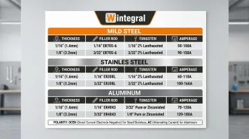
Comprehensive TIG Filler Rod Selection Chart
| Base Material | Thickness | Rod Diameter | Tungsten Size | Amperage Range |
|---|---|---|---|---|
| Mild Steel | 1/16" (1.6mm) | 1/16" (1.6mm) | 1/16" (1.6mm) | 95-135 A (DCEN) |
| 1/8" (3.2mm) | 3/32" (2.4mm) | 3/32" (2.4mm) | 145-205 A (DCEN) | |
| 1/4" (6.4mm) | 1/8" (3.2mm) | 1/8" (3.2mm) | 240-300 A (DCEN) | |
| Stainless Steel | 1/16" (1.6mm) | 1/16" (1.6mm) | 1/16" (1.6mm) | 80-100 A (DCEN) |
| 1/8" (3.2mm) | 3/32" (2.4mm) | 1/16" (1.6mm) | 120-140 A (DCEN) | |
| Aluminum | 1/16" (1.6mm) | 1/16" (1.6mm) | 1/16" (1.6mm) | 60-80 A (AC) |
| 1/8" (3.2mm) | 3/32" (2.4mm) | 3/32" (2.4mm) | 125-145 A (AC) |
Sizing Rules and Adjustment Factors
General rule: Filler rod diameter should be approximately equal to material thickness up to 1/8" (3.2mm). For thicker materials, use 1/8"-3/16" (3.2-4.8mm) rods.
The rod must be smaller than base metal thickness to prevent burn-through and overheating.
Application-Specific Adjustments
Adjustment factors:
- Out-of-position welding (vertical/overhead): Reduce rod size by one increment and lower amperage 10-20% for better puddle control
- High-deposition flat/horizontal welds: Increase rod size to maximise deposition rate
- Joint accessibility: Use smaller rods for confined spaces or complex repairs
Joint accessibility: Use smaller rods for confined spaces or complex repairs, particularly in tool and die repair work where precision is critical
Common Filler Rod Types and Applications
Selecting the right TIG filler rod depends on understanding material compatibility and service conditions. The classifications below cover the most common repair scenarios in mould and die work.
Carbon and Low-Alloy Steel Filler Rods
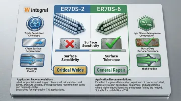
For carbon steel repairs, two classifications dominate: ER70S-2 and ER70S-6. The key difference lies in their deoxidizer chemistry and surface tolerance.
ER70S-2 vs. ER70S-6:
| Feature | ER70S-2 | ER70S-6 |
|---|---|---|
| Deoxidizers | Triple deoxidized (Zr, Ti, Al) | High silicon (0.80-1.15%) & manganese (1.40-1.85%) |
| Surface Tolerance | Requires clean steel | Excellent for rusty/dirty steel with mill scale |
| Fluidity | Moderate | High (better wetting) |
| Application | Critical single-pass welds | General repair, structural, imperfect surfaces |
ER70S-6 is the standard choice for mould repairs with imperfect surface conditions. Its higher silicon and manganese content acts as deoxidizers, producing cleaner welds on contaminated surfaces without extensive pre-cleaning.
Stainless Steel Filler Rods
The "L" designation indicates extra low carbon (0.03% max) to prevent carbide precipitation (chromium depletion) during welding, preserving corrosion resistance.
Key stainless classifications:
- ER308L: Standard for 304 stainless base metal; provides matching corrosion resistance for general atmospheric exposure
- ER309L: The "dissimilar metal" rod for joining stainless to carbon steel; high chromium/nickel content (23% Cr, 13% Ni) handles dilution from carbon steel side
- ER316L: The "marine" rod; contains molybdenum (2.0-3.0%) for superior pitting resistance in chloride environments
Aluminum Filler Rods: ER4043 vs. ER5356
The silicon vs. magnesium trade-off defines aluminum filler selection.
| Feature | ER4043 (Al-Si) | ER5356 (Al-Mg) |
|---|---|---|
| Composition | 5% Silicon | 5% Magnesium |
| Crack Sensitivity | Low (best for 6061) | Higher on 6061 |
| Shear Strength | Lower (75 MPa) | Higher (125 MPa) |
| Anodizing | Turns dark gray | Good color match |
| Temperature Limit | Good >150°F | Avoid >150°F (stress corrosion cracking risk) |
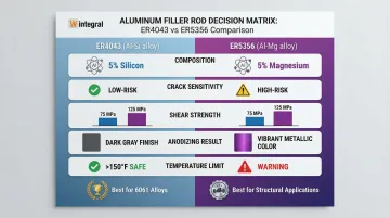
When to use each alloy:
ER4043 is preferred for 6061 groove welds due to lower crack sensitivity and better fluidity. It's the safer choice for general aluminium mould repairs.
Use ER5356 when parts will be anodized (better color match) or require higher shear strength and ductility in structural applications.
How Wintegral Engineering Can Help
Wintegral Engineering's expertise in precision mould and die repair includes proper filler rod selection as a critical quality control element.
Their multi-process welding capabilities—TIG, Micro-TIG, Laser, and Micro-Plasma—combined with correct filler rod matching ensure superior repair results with minimal heat-affected zones.
Key differentiators:
- Experience repairing thousands of precision moulds and dies with optimal filler rod selection across industries including pressure die casting, plastic injection moulding, and tool manufacturing
- Uses highest-grade welding materials from established global suppliers, ensuring consistent quality and metallurgical compatibility
- Maintains average welding defect rate less than 1% through proper material matching, expert micro-wire selection, and rigorous process control
Their systematic approach to filler rod selection evaluates multiple critical factors:
- Base metal chemistry and metallurgical compatibility
- Rod size selection based on joint configuration
- Hardness parameters and tensile property requirements
- Post-weld treatment specifications
This ensures weld deposits match the base metal exactly for materials including H-13, P-20, D2, M2, and SS420.
Conclusion
Successful TIG welding depends on selecting filler rods that match both the technical requirements of the base metal and the practical demands of the application. The goal is achieving reliable, defect-free welds that meet strength, corrosion resistance, and service life requirements specific to your manufacturing process.
No single filler rod works for all applications. To ensure optimal results:
- Consult AWS filler metal specifications (A5.18 for carbon steel, A5.9 for stainless, A5.10 for aluminum)
- Conduct test welds when uncertain about compatibility
- Consult welding specialists for critical repair applications where failure costs far exceed material investments
For precision repairs on tools, dies, and moulds, companies like Wintegral Engineering offer micro-welding expertise across multiple processes, helping Indian manufacturers achieve sub-1% defect rates on critical components.
Frequently Asked Questions
How to choose TIG filler rod size?
Select rod diameter approximately equal to material thickness up to 1/8", then use 1/8"-3/16" rods for thicker materials. Reduce size for vertical/overhead positions, increase for high-deposition flat welds.
What is the rule of 33 in TIG welding?
The rule suggests filler rod diameter should be roughly 1/3 of the base material thickness to maintain proper puddle control and heat input. This prevents overheating thin materials while ensuring adequate filler addition.
What is ER70S-2 TIG rod used for?
ER70S-2 is a triple-deoxidised mild steel filler rod used for welding carbon steels, particularly on clean surfaces where its deoxidisers produce high-quality welds in critical single-pass applications.
How to read TIG filler rod classifications?
AWS designations: "ER" indicates electrode or rod, the number shows minimum tensile strength in ksi (70 = 70,000 psi or 483 MPa), "S" means solid wire, and the final digit indicates composition and deoxidiser package.
Can you use the same filler rod for different base metals?
No. Filler rods must be compatible with base metal chemistry. Using incompatible rods causes cracking, poor fusion, or corrosion. Always match filler rod to base metal type, or use bridging alloys for dissimilar joints.