Introduction
TIG welding defects cost manufacturers significantly—research shows rework typically costs 2 to 3 times more than the original fabrication. When you're working with precision moulds, dies, or structural components, even minor porosity can reduce impact toughness by up to 38%, turning a functional weld into a potential failure point.
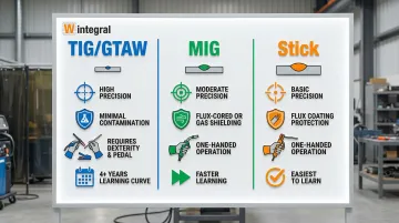
TIG (Gas Tungsten Arc Welding) produces the cleanest, most precise welds in manufacturing, but this precision comes with a steep learning curve. Unlike MIG or Stick welding, TIG offers little room for error—the weld pool is smaller, more sensitive to contamination, and every defect shows immediately.
This guide covers:
- How to identify the six most common TIG welding defects
- Root causes behind each defect type
- Specific fixes you can apply immediately
- When professional repair services become the more economical choice
Key Takeaways
- Porosity from contamination or poor shielding—clean thoroughly and verify 15-20 CFH gas flow
- Contamination shows as discoloration—correct polarity and increase gas coverage
- Reduce amperage 10-15% and slow travel speed to prevent undercut grooves at weld toe
- Tungsten inclusion requires complete removal—prevent by never touching electrode to weld pool
- Lack of fusion demands complete removal and re-welding—adding more passes won't fix it
- Professional micro-TIG services often cost less than risking damage to high-value moulds and dies
What Is TIG Welding?
TIG welding, or Gas Tungsten Arc Welding (GTAW), uses a non-consumable tungsten electrode to create an arc that melts the base metal, while an inert shielding gas (typically argon or helium) protects the weld pool from contamination from air. The welder adds filler metal separately when needed, giving complete precise control over heat input and deposition.
This precision makes TIG the preferred choice for applications requiring superior aesthetics, tight tolerances, and minimal distortion.
Common applications in Indian manufacturing include:
- Mould and die repair: Controlled heat input minimizes distortion on expensive tooling
- Pressure die casting: Repairs to HPDC and LPDC moulds without warping
- Plastic injection moulding: Precision repairs to mould cores and cavities
- Metal machining: Joining dissimilar metals in production tooling
However, TIG demands significantly more skill than other welding processes. The process requires simultaneous coordination of both hands (torch and filler rod) plus often a foot pedal for amperage control, while maintaining precise arc length of just 2-3mm.
Studies show that welders with less than 4 years of GTAW experience produce lack of penetration defects 4 times more frequently than senior welders—particularly among those transitioning from Stick welding without proper TIG-specific training.
Common TIG Welding Defects
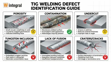
Visual inspection remains the first and most effective method for identifying TIG weld quality issues. Understanding what each defect looks like helps you diagnose the root cause quickly.
Porosity (Gas Pockets)
Symptoms: Small holes or voids visible on the weld surface, or a "Swiss cheese" appearance when the weld is cut or broken open.
Porosity accounts for 25% to 36% of all TIG welding defects, making it the most common problem you'll encounter.
Common causes include:
- Contaminated base metal (oil, grease, paint, moisture, rust)
- Inadequate shielding gas coverage or flow rate too low
- Moisture in gas lines or contaminated gas supply
- Drafts or wind disrupting gas flow around the weld pool
- Hydrocarbons from fingerprints or residual cleaning solvents
Contamination and Discoloration
Symptoms: Brownish, black, or gray discoloration on the weld bead; grainy or flaky appearance; inconsistent bead color.
On stainless steel root passes, severe oxidation creates a dark, crusty "sugaring" formation that destroys corrosion resistance.
Root causes:
- Oxidation due to insufficient shielding gas coverage
- Wrong polarity (especially critical on aluminum—must use AC, not DCEN)
- Contaminated filler rod or dirty base material
- Lack of back purging on stainless steel pipe/tube welds
- Oxygen levels exceeding 50 ppm during welding
Undercut
A groove or depression forms along the weld toe where base metal melts away faster than filler metal can replace it. This reduces the weld's structural strength and creates weak points prone to failure.
What causes it:
- Excessive amperage melting base metal faster than filler can fill
- Arc length too long (electrode too far from work)
- Travel speed too fast for proper fusion
- Improper torch angle preventing adequate toe filling
Tungsten Inclusion
Dark spots or hard particles embedded in the weld, often discovered only during radiographic inspection or when the weld fails. Tungsten appears as bright white spots on X-rays due to its extremely high density.
Primary causes:
- Touching tungsten electrode to the weld pool or filler rod
- Using tungsten diameter too small for the amperage setting
- Improper tungsten preparation or contaminated electrode
- Excessive current causing tungsten to melt and transfer into weld
Lack of Fusion/Poor Penetration
Weld bead sits on top of base metal without bonding; incomplete root penetration in groove welds; "cold lap" appearance where the weld didn't fuse into the base metal.
This critical structural defect can account for up to 18% of defects in complex applications like tool and die repair.
What triggers this defect:
- Insufficient amperage for material thickness
- Travel speed too fast
- Improper joint fit-up with excessive gaps
- Arc length too long, reducing heat concentration
Craters and Cracks
Depression at weld end that often develops star-shaped cracks radiating from the crater. These cracks can spread under load, leading to catastrophic failure—a concern particularly critical in precision mould and die applications.
Common triggers:
- Abruptly stopping arc without using crater fill sequence
- Removing filler rod too quickly at weld termination
- Insufficient current taper at weld end
- High restraint or rapid cooling promoting hot cracking
At Wintegral Engineering's welding studios, maintaining a defect rate below 1% requires recognizing these symptoms early and addressing root causes systematically—especially when repairing high-value moulds and dies where even minor defects compromise tool performance.
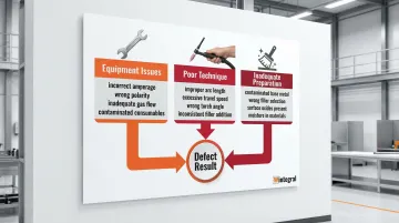
Why TIG Welds Fail
TIG welding defects stem from three primary categories: improper equipment settings (amperage, gas flow, polarity), poor technique (arc length, travel speed, filler addition), and inadequate preparation (dirty materials, wrong consumables). Understanding which category caused your defect is the first step toward fixing it.
Unlike MIG or Stick welding, TIG provides minimal margin for error. The weld pool is smaller and more sensitive to contamination.
MIG has flux-cored wires or shielding gas that can scavenge some impurities; Stick welding has flux coating that provides similar protection. TIG has only the inert shielding gas. If that protection fails for even a moment, contamination occurs instantly.
This sensitivity means defects carry serious consequences:
- Structural applications: Minor porosity can reduce impact toughness by 4% to 38% in critical steel components
- Production rework: Rejected parts trigger costs that typically reach 2 to 3 times the original fabrication expense
- Pressure vessels and piping: Defects discovered after commissioning may require complete system replacement
- Mould and die repair: Failed welds on expensive tooling can mean scrapping components worth ₹50,000 to ₹5,00,000 or more
Welding codes reflect these serious consequences. AWS D1.1 for structural steel mandates zero tolerance for cracks. ASME B31.3 for process piping similarly prohibits cracks and incomplete fusion entirely.
These aren't arbitrary standards—they're based on decades of failure analysis showing that certain defects inevitably lead to service failures.
How to Fix Common TIG Welding Defects
The fix depends entirely on defect type and severity. Some require only parameter adjustments for future welds, while others demand complete weld removal and rework.
Never attempt to "fix" a structural defect by simply adding more weld on top—this only hides the problem and can lead to catastrophic failure under load.
Fixing Porosity
Preventing porosity in future welds requires addressing contamination sources:
- Clean base metal thoroughly using acetone or approved solvent, followed by mechanical cleaning
- Use dedicated stainless steel brush for aluminium (never use the same brush on steel—cross-contamination causes porosity)
- Check shielding gas flow rate: 15-20 CFH (7-9 L/min) for most applications
- Inspect gas lines and connections for leaks using soapy water test
- Protect weld area from drafts with welding screens or barriers
- Verify gas purity—use welding-grade Argon (99.995%+)
- Check for moisture in gas lines, especially after cylinder changes
Existing porous welds require assessment before repair:
- Minor scattered porosity (1-2 small pores) may be acceptable in non-critical applications
- Clustered or linear porosity requires action—these indicate systematic contamination
- Complete weld removal by grinding to sound metal
- Clean thoroughly before re-welding with corrected parameters
- Consider radiographic testing to verify complete defect removal in critical applications
Fixing Contamination and Discoloration
Contamination manifests differently across materials. For aluminium welding:
- Verify polarity is set to AC (alternating current), not DCEN
- Adjust AC balance control to increase cleaning action—decrease balance percentage to increase electrode positive time, which breaks up surface oxides
- Clean aluminium with dedicated stainless steel brush immediately before welding (oxide layer reforms in minutes)
- Remove any anodizing or coating in the weld zone
- Preheat slightly if working with thick sections to reduce thermal shock
Stainless steel requires different approaches to minimize heat tint:
- Reduce amperage by 10-15% or increase travel speed to minimize heat input
- Use back purging with argon for tube/pipe welds—oxygen levels must be below 50 ppm, ideally under 25 ppm
- Consider pulsing technology to control heat and reduce oxidation
- If significant discoloration has occurred, weld properties are compromised—removal and rework may be required for critical applications
- Light heat tint (straw/gold color) is generally acceptable; dark blue, purple, or black indicates excessive oxidation
Fixing Undercut
Undercut results from excessive heat or poor technique. Adjust these parameters:
- Reduce amperage setting by 10-15% and retest
- Shorten arc length—keep tungsten closer to work (1/8 inch or less)
- Slow travel speed to allow weld pool to properly fill toes
- Adjust torch angle slightly toward direction of travel to improve wetting action
- Add filler metal more consistently to build adequate reinforcement
When evaluating existing undercut:
- Minor undercut (less than 1/32 inch deep) may be acceptable per AWS D1.1 for statically loaded structures
- Deeper undercut significantly reduces load-bearing capacity—requires weld removal and rework
- Measure depth with a gauge to determine if code limits are exceeded
- For critical applications, any undercut may be cause for rejection
Fixing Tungsten Inclusion
Tungsten inclusions compromise weld integrity. Prevention requires careful electrode management:
- Never allow tungsten to touch weld pool or filler rod
- Increase tungsten diameter if working at high amperage—consult manufacturer's amperage rating charts
- Properly prepare tungsten tip geometry: grind longitudinally (parallel to rod), not radially
- Use truncated (flat) tip for high-amperage DC to prevent tip shedding
- Replace contaminated electrodes immediately
Existing tungsten inclusions cannot be left in place:
- Tungsten inclusions must be completely removed—no exceptions
- Grind out affected area completely (tungsten is extremely hard and brittle)
- Extend grinding beyond visible inclusion to ensure complete removal
- Clean thoroughly and re-weld with corrected technique
- Radiographic or ultrasonic testing may be required to verify complete removal in critical applications
Fixing Lack of Fusion/Poor Penetration
Lack of fusion indicates insufficient heat input or contamination. Address these factors:
- Increase amperage in 5-10 amp increments until achieving proper penetration
- Slow travel speed to allow more heat input per unit length
- Shorten arc length for better directional control and heat concentration
- Ensure proper joint fit-up—excessive gaps (over 1/16 inch) cannot be bridged with TIG
- Verify base metal cleanliness—mill scale or oxides prevent fusion
When fusion defects are discovered:
- Weld must be completely removed and redone—this is a critical structural defect
- Lack of fusion cannot be repaired by adding more weld on top
- Grind to sound base metal before re-welding
- Consider ultrasonic testing to verify complete removal of the defect
Fixing Craters and Cracks
Craters form when the arc is broken too abruptly. Professional welding facilities like Wintegral Engineering's precision repair services emphasize proper termination to avoid these defects.
Correct termination technique includes:
- Use crater fill function on TIG machine if available (gradually reduces current while continuing filler addition)
- Manually taper current down slowly while feeding filler rod into crater
- Keep arc on the crater while reducing amperage to allow proper filling
- Practice proper weld termination on scrap material
Craters that have already cracked require complete removal:
- Grind out crater and crack completely
- Extend grinding beyond visible crack ends (cracks often extend further than visible)
- Use dye penetrant testing to verify complete crack removal
- Re-weld with proper termination technique
- Cracks can propagate under load, making complete removal essential—never weld over a crack
When to Fix vs. Redo vs. Hire a Professional
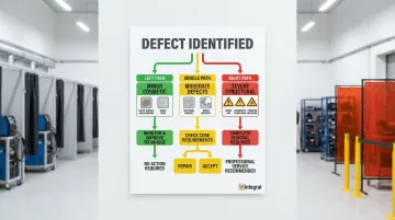
Not all TIG weld defects are equal. Some are cosmetic, others are structural failures. Your decision depends on application criticality, code requirements, and the cost of failure.
Minor Cosmetic Defects
Slight discoloration (light straw or gold color), minor ripple irregularity, or a single small isolated pore are generally acceptable for non-critical applications.
No action needed unless aesthetics matter to the customer or application. Focus on improving technique for future welds rather than reworking acceptable welds. Professional services aren't necessary unless specified by customer requirements or welding code.
Moderate Defects
Scattered porosity (3-5 small pores), minor undercut (less than 1/32 inch), or slight lack of fill may be acceptable depending on welding code.
AWS D1.1 for structural steel and ASME B31.3 for process piping have specific acceptance criteria. Verify against applicable standards before deciding. Consider professional inspection by a Certified Welding Inspector (CWI) for code-critical work—especially for borderline cases where professional evaluation prevents costly mistakes.
Severe Structural Defects
These defects cannot be "fixed"—they're reject-quality welds that compromise structural integrity:
- Lack of fusion
- Cracks (any size)
- Tungsten inclusion
- Severe undercut (deeper than 1/32 inch)
- Excessive or aligned porosity
Welding codes mandate zero tolerance for cracks and incomplete fusion. Complete removal and rework required.
For high-value moulds, dies, or critical components, professional TIG welding services with specialized equipment may be more cost-effective than risking further damage. Wintegral Engineering's multi-process capabilities (including micro-TIG and hybrid laser-TIG) achieve defect rates below 1%, significantly reducing the risk of repeated failures.
Precision/High-Value Components
For injection moulds, die-casting dies, aerospace parts, pressure vessels, or tooling worth ₹50,000 or more, DIY repairs carry high risk.
The stakes for precision components:
- Additional heat damage from improper technique
- Distortion affecting dimensional accuracy
- Repeated defects on expensive tooling
- Heat-affected zones compromising precision
Specialized mould and die repair services offer advanced processes (micro-plasma, laser-TIG hybrid) with precise heat control.
Wintegral Engineering's laser welding systems produce deposits as small as 100 microns with minimal heat-affected zones, preventing the distortion that often occurs with conventional TIG repairs. Their permanent repair solutions restore original hardness without requiring additional heat treatment.
For expensive tooling, professional services are often more economical than scrapping components or risking further damage through trial-and-error repairs.
When You Lack Proper Equipment or Expertise
TIG welding requires specific equipment and significant skill development:
- Proper amperage range for material thickness
- AC/DC capability for different metals
- Pulse functions for heat-sensitive materials
If you're welding outside your experience level—exotic alloys, thin-gauge precision work (under 1mm), or code-critical applications—the learning curve is expensive.
Services with proven track records reduce risk and total cost. Look for facilities offering multiple welding processes, quality assurance systems, and experience with your specific material and application.
Wintegral Engineering's multi-city facilities handle tooling from small inserts to 20+ ton moulds, with technical teams trained to select the most economical and fastest welding process for each specific repair requirement.
Preventive Measures to Avoid Future TIG Welding Defects
Prevention costs far less than repair. Consistent pre-weld routines, equipment maintenance, and skill development form the foundation of defect-free welding.
Pre-weld preparation routine:
- Dedicate separate tools for each material type—never use the same stainless steel brush on both aluminum and steel
- Clean base metal with approved solvent (acetone, alcohol) followed by mechanical cleaning
- Clean filler rod immediately before welding—even fingerprints introduce contaminants
- Verify proper filler metal type and size for the application
- Remove all paint, rust, mill scale, and coatings from the weld zone
Proper material preparation means nothing without reliable equipment. Regular maintenance prevents arc instability and gas coverage issues.
Equipment maintenance and verification:
- Check shielding gas flow rates before each welding session using a flowmeter
- Inspect gas lines, fittings, and torch consumables for leaks or wear
- Perform leak testing with soapy water on all connections monthly
- Maintain proper tungsten inventory (correct sizes and types for different materials)
- Ensure consistent electrical ground connection—poor ground causes arc instability
- Replace worn collets, collet bodies, and gas lenses that disrupt laminar gas flow
Technical capability separates acceptable welds from exceptional ones. Continuous skill development reduces defect rates over time.
Skill development and documentation:
- Practice maintaining consistent arc length (1/8 inch or less) and travel speed
- Learn material-specific settings: AC balance for aluminum, pulse parameters for stainless steel, amperage per thickness rules
- Consider inverter-based machines with advanced controls for better arc stability and heat management
- Document successful parameter sets for recurring jobs—create a reference library
- Pursue formal training and certification through programs like AWS SENSE
- Practice on scrap material when learning new techniques or materials
Practice on scrap material when learning new techniques or materials
For precision welding operations where defect rates must stay below 1%, companies like Wintegral Engineering combine these preventive practices with process-specific expertise across multiple welding technologies, demonstrating how systematic prevention delivers consistent results in high-stakes industrial applications.
Conclusion
You can prevent most TIG welding defects through proper technique, equipment settings, and material preparation. Visual inspection combined with understanding defect causes allows rapid troubleshooting—you can often identify the root cause within seconds of seeing the weld.
The fixes range from simple parameter adjustments (reduce amperage by 10% for undercut) to complete weld removal and rework (for cracks or lack of fusion).
Knowing when to fix, redo, or seek professional help is critical for cost management and quality assurance:
- Minor cosmetic defects rarely require action on non-critical work
- Structural defects demand complete removal—never weld over cracks or lack of fusion
- High-value components (moulds, dies, precision tools) benefit from professional services with specialized equipment
Professional intervention prevents the costly cycle of repeated failures that often occurs when attempting complex repairs without proper training or tools. Wintegral Engineering's experience repairing thousands of precision moulds and die-tools shows that specialized repair services deliver lower total cost through permanent fixes. These repairs restore original performance without additional heat treatment or dimensional loss.
Frequently Asked Questions
What is the difference between a good and bad TIG weld?
A good TIG weld shows consistent bead width, uniform ripple pattern, proper penetration, and color matching the base material (light straw/gold for stainless). Bad welds display porosity, undercut, dark contamination, inconsistent beads, or lack of fusion.
What causes porosity in TIG welding and how do I prevent it?
Porosity results from contamination (oil, moisture, rust), inadequate shielding gas coverage, or drafts disrupting gas flow. Prevent by cleaning materials with solvent and dedicated brushes, maintaining 15-20 CFH gas flow, and shielding the weld from wind.
How do I know if my shielding gas flow rate is correct?
Proper flow is typically 15-20 CFH (7-9 L/min) for most TIG applications using argon. Check manufacturer recommendations for your torch and cup size, then adjust based on weld results—if you see oxidation or porosity, increase flow slightly.
Why does my aluminum TIG weld look contaminated or discoloured?
Aluminium contamination usually indicates wrong polarity (must use AC, not DC), insufficient AC balance cleaning action, or surface oxides not removed before welding. Always verify AC polarity, adjust balance control to increase cleaning, and use a dedicated stainless steel brush immediately before welding.
Can a bad TIG weld be repaired or does it need to be completely redone?
Minor cosmetic defects (slight discolouration, small isolated pores) may be acceptable depending on application requirements. Structural defects—lack of fusion, cracks, severe undercut, tungsten inclusion—require complete removal and re-welding.
When should I hire a professional welding service instead of fixing it myself?
Hire professional services for high-value components (moulds, dies, precision tools), code-critical applications requiring certified procedures, exotic materials outside your expertise (titanium, Inconel), or when repeated DIY attempts cause additional damage. Companies like Wintegral Engineering specialise in precision mould and die repair using advanced micro-welding processes with less than 1% defect rates.